SPLASh (Stereotactic PLAnning Software)
Daniel Sperka and Jochen Ditterich
04/12/2011 (Updated: 09/04/2019)
1. Introduction
SPLASh is an add-on tool integrated into Caret [1]. It is designed to aid in the placement of recording chambers to optimize access to the target area. Regions that can be accessed by a particular recording chamber placement can be shown on Caret's flat map or in the structural MRI volume. In addition, the tool allows for exploring individual electrode tracks. The current version of SPLASh has been re-integrated into a fork of the latest version of caret available at NeuroDebian. No modifications have been made the caret code base beyond what was available at NeuroDebian, and all functionality available in the NeuroDebian version is also available in SPLASh.
[1] //Van Essen, D.C., Dickson, J., Harwell, J., Hanlon, D., Anderson, C.H. and Drury, H.A. 2001. An Integrated Software System for Surface-based Analyses of Cerebral Cortex. Journal of American Medical Informatics Association, 8(5): 443-459.//
1.1. Overview
Animal researchers typically rely on 2D standard brain atlases for stereotactic planning. This approach can be tedious and error prone, however, and individual anatomic differences cannot be taken into account. SPLASh uses the standard atlases available with Caret [2]. By integrating 3D models of the subject's skull and brain surface (extracted from a structural MRI volume) the tool computes stereotactic coordinates for cylinder placement, and can highlight accessible areas in both the MRI volume and flat maps.
SPLASh will let you create a "trajectory file" that can be saved and loaded in Caret. The trajectory file stores a set of "trajectories". The SPLASh dialog lets you create, modify and delete trajectories. SPLASh highlights nodes accessible by the currently active trajectory in both the flat maps and the MRI volume. The placement of the cylinder on the skull is displayed with Caret's fiducial surface.
The version linked below runs on the latest Ubuntu release, 18.04.
[2] Van Essen, D.C. (2002) Windows on the brain. The emerging role of atlases and databases in neuroscience. Curr. Op. Neurobiol. 12: 574-579
1.2. Giving us credit and SPLASh tutorial
If you decide to use SPLASh in work that is published, please cite this article. The article can also serve as a more extensive tutorial on the capabilities of the tool.
1.3. Downloading and installing SPLASh
The latest version of SPLASh was built and tested on Ubuntu 18.04. It can be downloaded here. To install from the command line, first remove any previous version of caret. Then,
dan@dev:~/Desktop> sudo dpkg -i caret_5.6.6~dfsg.1-1.3_amd64.deb
1.4. Downloading data for SPLASh
SPLASh uses the SumsDB Macaque atlases for either the left or right hemisphere [3]. Download one of these and unpack it to a newly-created folder. THIS IS IMPORTANT - you must keep each hemisphere's data in its own folder!!!
SPLASh also requires data files not provided in the SumsDB atlas. Our additions include data files containing the skull and brain surface (which are extracted from the MRI images in the SumsDB atlas), a modified spec file and a seed data file for use with the SPLASh tool. Download these modifications/additions for the left or right hemisphere and unpack them into the same folder as that hemisphere's data.
dan@dev:~/Desktop> mkdir SPLASh-Data-L dan@dev:~/Desktop> cd SPLASh-Data-L dan@dev:~/Desktop/SPLASh-Data-L> tar xzvf ../MACAQUE.LEFT_HEM.04-01-29.tar.gz dan@dev:~/Desktop/SPLASh-Data-L> tar xzvf ../Macaque.F99.L.modifications_additions.tar.gz
[3] Data courtesy of the Van Essen Laboratory, Washington University in St. Louis.
1.5. Running SPLASh and opening the spec file
SPLASh can be run with the command splash or caret5.
Open a spec file by choosing File>Open Spec File. Navigate to the folder where you unpacked the data files and select the spec file Macaque.F99UA1.Cerebral.L.Traj.INTERAURAL.04-01-29-34132.spec. Make certain that the anatomy volume file is selected (the SPLASh tool requires this). Alternatively, hit Select All. Hit the Load button to load the data files.
Remember that SPLASh is based on //Caret-5.3. However we do not provide a complete distribution of Caret: there are no command-line utilities, and some Caret functionality is disabled. For a full distribution of Caret, see the Caret website. Neurodebian also has a version available (the version that our tool is based on).
1.6. Opening the SPLASh Dialog
The SPLASh dialog is opened from Caret's Volume menu. There are three tabs: General, Path and Settings. The General tab is for creating, renaming and removing saved trajectories. The tools on this tab are also used to specify and display the target position and recording cylinder placement for each trajectory. Trajectory path details and settings are controlled from the "Path" tab. The "Parameters" tab controls display colors and physical dimensions for the recording cylinder.
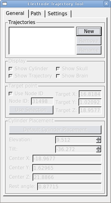
1.7. Creating a New Trajectory
To create a new trajectory open the SPLASh dialog from Caret's main menu: Volume>SPLASh Tool. Click "New" and give your trajectory a name. Next we must define a target point and place a recording cylinder.
Define a target node by selecting a node in Caret's flat map. Hit "Use Selection" to make the selected node the target node. (Making a selection from the MRI volume is not supported at this time.) To use a specific node number as the target, check "Use node ID" and enter the node number.
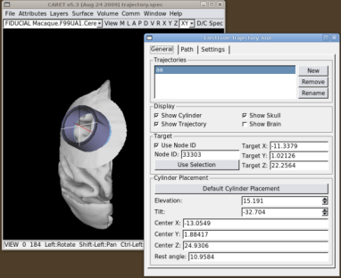
Once you've chosen the target, hit the "Default Cylinder Placement" button. This will place the cylinder at the closest possible point on the skull, oriented such that its symmetry axis passes through the target node. The display checkboxes allow you to turn parts of the trajectory display on and off. "Show Trajectory" displays the trajectory path at the currently selected grid position, and it shows nodes within the Search Path on the MRI volume and flat maps. "Show Skull" ("Show Brain") display the region of skull (brain) within a small radius of the cylinder. "Show Cylinder" displays the cylinder and its central axis.
The position and orientation of the recording cylinder can be changed with the "Elevation" and "Tilt" spinboxes. As the recording cylinder is moved, The tool places the recording cylinder so that its symmetry axis always passes through the target node. The "Elevation" is the angle between the cylinder's symmetry axis and the coronal (XZ) plane. Rotations towards the front of the head (resulting in a posterior-going component of the electrode tip as the electrode is advanced) are considered positive. Rotations towards the rear (resulting in an anterior-going component of the electrode tip as the electrode is advanced) are negative. Similarly, the "Tilt" is the angle between the symmetry axis of the cylinder and the sagittal (YZ) plane. Cylinder tilts to the left (resulting in a rightward-going component of the electrode tip as the electrode is advanced) are negative. Cylinder tilts to the right (resulting in a leftward-going component of the electrode tip as the electrode is advanced) are positive. At each cylinder position we estimate the angle that the base of the cylinder makes with the skull surface (this is shown in the "Rest Angle" box).
1.8. Modifying the search path
When "Show Trajectory" is checked, the SPLASh tool will highlight nodes from Caret's fiducial surface that are close to the currently defined trajectory path. These nodes are displayed (using colors specified on the "Settings" tab) on the flat map and MRI volume display windows. The "Path" tab allows you to manipulate the search area used to find displayed nodes and voxels. The search area is a cylinder centered on the current trajectory path. The radius of the search cylinder can be specified in mm. By default the search is along the entire trajectory, however the depth of the search can be limited by checking "Use Depth Tool". When the depth tool is in use the search path is limited to within a small tolerance (in mm) of a depth controlled by the slider widget. The indicated depth is relative to the extracted brain surface (not the skull and not the fiducial surface, which reflects layer 4 of the cortical sheet).
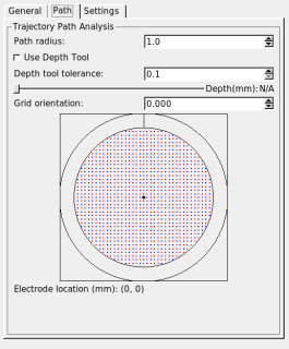
You can choose alternate trajectory paths by selecting points on the grid widget. Grid locations can be selected with a resolution of 0.5 mm. The positive y-axis in the grid widget (indicated by the short vertical line between the two circles) corresponds to the dark line in the crosshairs displayed in the 3D rendering of the recording cylinder.
The orientation setting lets you rotate your grid (positive angles are clockwise rotations; negative angles are counter-clockwise rotations). The orientation of the widget's grid does not change as you change the orientation, but the crosshairs and the electrode location in the 3D rendering do.